Pages

Search This Blog

Saturday, August 2, 2014

What is Permeability ?

"Permeability" is measure of a porous rock system how easily it allows fluids to move through it. The common unit of permeability is "milli darcy", represented by "mD". Figure-1 illustrates the fluid flow path through the effective pore spaces.
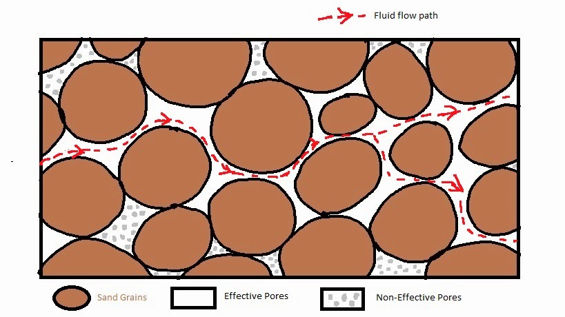
Figure-1
A rock can be highly porous, that is have high porosity, but may have low permeability or vice-verse.

"Absolute Permeability" is the permeability in a porous medium as such sand stone for a single fluid like oil or water.

"Effective Permeability" is the permeability of a given fluid (such as oil or water or gas)  in presence of another fluid in a porous medium.

"Relative Permeability" is the ratio of "Effective Permeability" for a given fluid in presence of another fluid to the absolute permeability of the porous medium.

What is Porosity

"Porosity" is the measure of pore spaces of a porous media. Mathematically,
Porosity = (Bulk Volume - Matrix Volume) / Bulk Volume = Pore Volume / Bulk Volume

where
Bulk Volume = the total volume occupied by a given rock body in 3D
Matrix Volume = the volume occupied by the rock grains
Pore Volume = the volume occupied by the space in between the rock grains.
Figure-1

In Figure-1 the outer black rectangle represents the "Bulk Volume", "Matrix Volume" or sand grains and between the  "Pore Spaces" or "Pore Volume" are represented in brown and white color respectively.

It is represented by the Greek letter ϕ (phi).

"Total Porosity" is the ratio of total pore space irrespective of weather they are connect or not to the bulk volume. "Effective Porosity" is the ratio of connected pore spaces to the bulk volume. This is the actual pore space from where fluid can flow to the producing wells (Figure-2).

Figure-2

Friday, August 1, 2014

What is PVT Analysis?

An important task that the Reservoir Engineers carries out is Fluid Characterization or PVT (Pressure-Volume-Temperature) Analysis. The objective is to define the hydrocarbon fluid system present in a given reservoir and model it a computer program. A number of experiments are conducted on carefully collected fluid samples and a mathematical equation is calibrated to represent them. The equations known as "Equation of State" (EOS), are then used to predict the behavior of the fluid in different reservoir and surface pressure-temperature conditions.

What is Artificial Lift ?

When the reservoir pressure is not sufficient to lift hydrocarbon from the bottom of the well to the surface, the lift mechanism employed to lift them to the surface and transport to the nearest collecting or separating facilities is called "Artificial Lift". The following list gives some commonly used artificial lift systems:

  • Gas Lift (GL)
  • Rod Pump / Sucker Rod Pump
  • Electrical Submersible Pump (ESP)
  • Hydraulic Pump
  • Progressing Cavity Pump (PCP)

What is Drive Mechanism?

Natural "Drive Mechanism" of a hydrocarbon reservoir is the natural energy available to push fluid from different parts of the reservoir to the producing well. There are a number of drive mechanisms identified. Often, more than one mechanism act simultaneously on a reservoir. The following is a list of most common drive mechanism:

  • Aquifer Drive / Water Influx
  • Gas Cap Expansion Drive
  • Solution Gas Drive
  • Gravity Drainage